{"name":"Fractal-mosaics","tagline":"Photomosaics 3.0","body":"#[UNDERCONSTRUCTION]\r\n\r\n\r\n\r\n#ImageRegistrationAlgorithmSteps\r\n\r\n1.Createlowresolutionversionsoftargetimage\r\n\r\nForeach“level”(levelsareexplainedshortly),werequirefivedifferentresolutionsofthetargetimage.\r\n\r\nFirst,wecreatethelowestresolutionversionofthetargetimage.Because8x8imageswerefound(inthisauthor’sexperiments),tobethelowestresolutionimagescapableofproducingmeaningfulrotationandscaleestimates,thelowestresolutiontargetimageiscomposedof8x8images,or“tiles”.Forexample,Figure6showsatargetimageofAbrahamLincolnatfullresolution(3072x2606pixels),andan8x8resolutionversion(24x20pixels).\r\n\r\n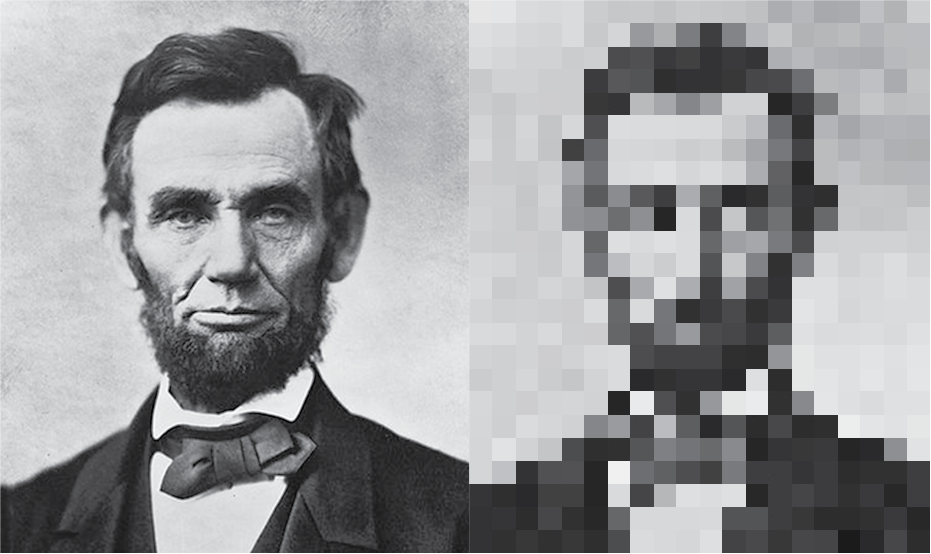\r\n\r\nNote that the low resolution version is three 8x8 “tiles” high. In other words, the largest possible images in the final mosaic will be approximately 1/3 of the mosaic height. This is a reasonable assumption, as we’re very unlikely to find a random library image that exactly matches more than a third of the target image.\r\n\r\nNext, we create the intervening resolutions. These resolutions are powers of two derived from the 8x8 image, up to 128x128. I.e., we have an 8x8 resolution image, as shown in Figure 6, a 16x16 resolution image which is four times the size of the 8x8 resolution image, a 32x32 resolution image which is four times the size of the 8x8 image, and so on, down to 128x128. 128x128 is the highest resolution we perform image registration on because higher resolutions do not produce meaningful refinements of scale and rotation and are therefore a waste of computation. The original library images (used to render the final mosaic) are 256x256 pixels.\r\n\r\nNote that while black and white images are used in this example, the same math applies to color. The same steps are simply applied to each color channel (R,G,B) in parallel.\r\n\r\n2. Perform Log-polar registration on each pixel\r\n\r\nSince Fractal Mosaics doesn’t perform “wrapping” of pixels on the boundary of the target image, we only evaluate pixels in the “valid pixel area” (red box in Figure 7).\r\n\r\n\r\n\r\nFor each location (x,y) in the valid pixel area, we perform the following steps:\r\n\r\n\r\n1. Crop 8x8 pixel portion of target image around pixel x,y. This is the “target tile” IT. Figure 8 shows an example crop, with the red pixel at x,y.\r\n\r\n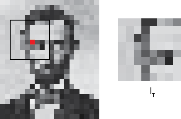\r\n\r\n\r\n2. Input target tile IT into image search module. The image search module returns a list of library images most statistically similar to the target tile. Details on this found in the Image Search section. The number of images returned is set via the ‘num_lib_test_pix_v’ parameter, as explained in the Variables page.\r\n\r\n3. For each library image returned by Step 2:\r\n\r\n1. Resize library image IL being evaluated to 8x8 pixels\r\n2. Take Log-polar transform of target tile IT and library image IL\r\n3. Compute cross-correlation of Log-polar transformed IT and IL\r\n4. Find maximum of cross-correlation and compute rotation and scale estimate from position of maximum.\r\n5. Rotate and scale library image by estimated scale and rotation.\r\n6. Compute rms error between scaled and rotated library image and target tile\r\n7. If rms error is below a threshold (i.e. good enough match), proceed to next resolution.\r\n\r\nIf the rotated and scaled 8x8 library image produces a low enough rms error, the above steps are repeated at the next resolution up, 16x16. Simply replace ‘8x8’ with ‘16x16’ in step 1 and the steps are